Update mined status of activity areas
As mining progresses, activity areas become partially or fully depleted. If these areas aren’t updated, the schedule will overstate available reserves and misrepresent the current face position. XECUTE provides tools to configure the mined status of activity areas so your plan reflects reality.
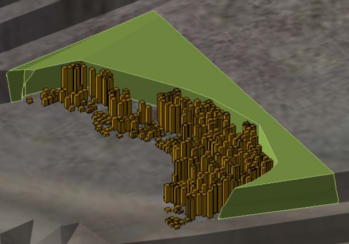
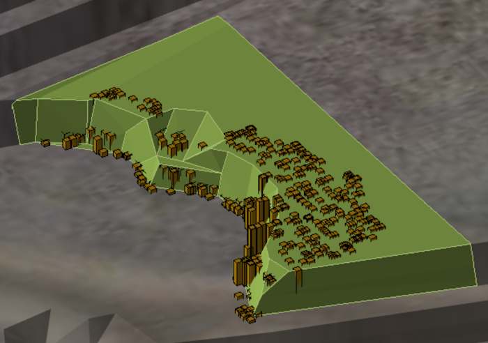
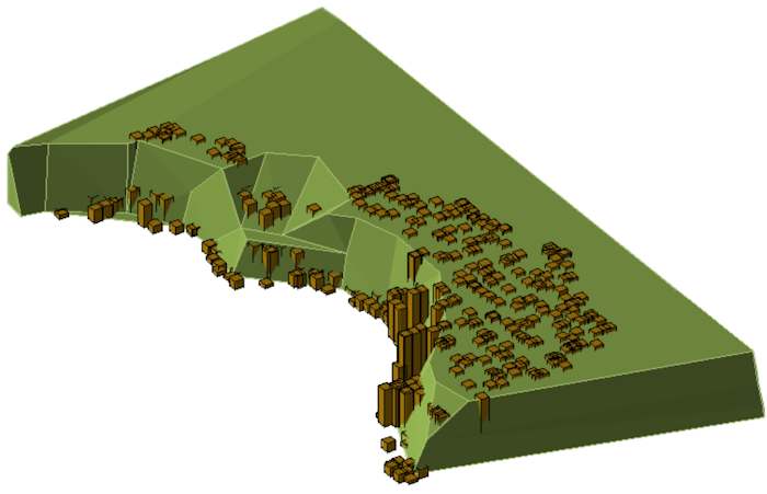
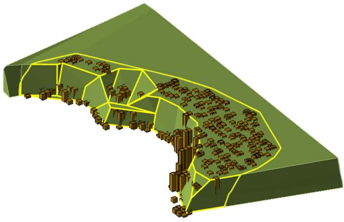
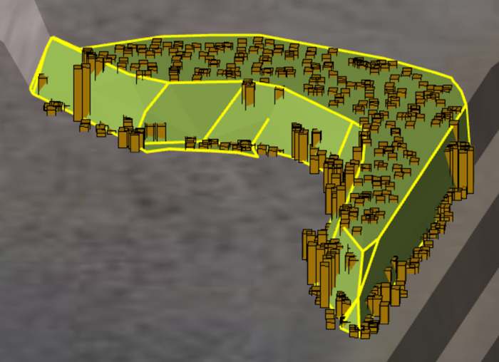
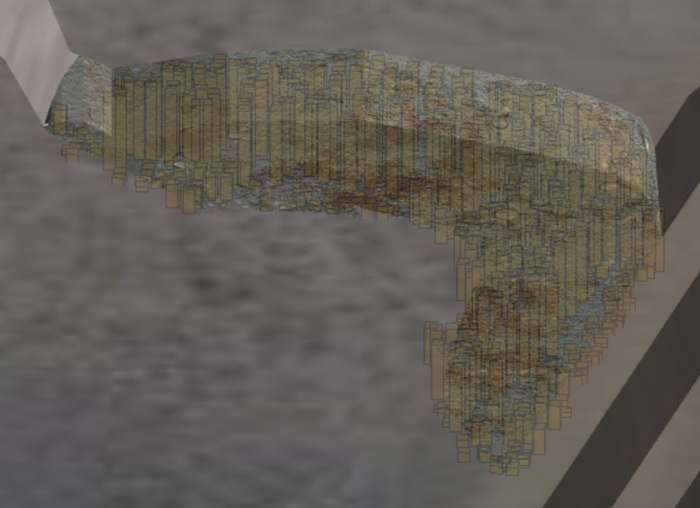
Before and after converting fully mined activity areas to mined-out. This reflects the actual status of activity areas at the start of the current planning horizon.
When do I update the mined status?
The mined statuses of a site’s activity areas should be accurate at the start of the scheduling horizon (refer to Update calendar). As such, whenever you update your scheduling horizon, whether that’s daily or weekly, you should update the mined status at the same time.
Why update mined status?
Updating the mined status ensures:
-
Accurate scheduling: Prevents assigning resources to depleted ground.
-
Correct reporting: Keeps production and compliance reports aligned with actual progress.
-
Updated topography: Reflects mined-out areas in the 3D scene and schedule animation.
Methods for updating mined status
You can update mined status in two ways:
-
Convert fully mined activity areas to Mined Out
Use this when an activity area has been completely mined.
-
Trim partially mined activity areas
Use this when only part of an activity area has been mined. You can trim using:
-
Bucket positions (preferred for accuracy).
-
A manually drawn mined-out polygon (when bucket data is unavailable).
-
Mined-out activity
Refer to Define Activities for more information about the Mined-Out activity.
You indicate how much an activity area is mined by allocating it, or a portion of it, to the Mined-Out activity.
A mined-out activity area represents ground where all material has been extracted. It’s a special system-defined activity type in XECUTE that marks an area as fully depleted at the start of the schedule. Using mined-out status is a quick way to update the plan and reflect the current face position.
When you apply the mined-out status:
-
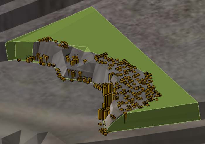
The software cuts the activity area’s shape into the topography.
-
This adjustment updates the topography so it reflects the mined-out state in the 3D scene and schedule animation.
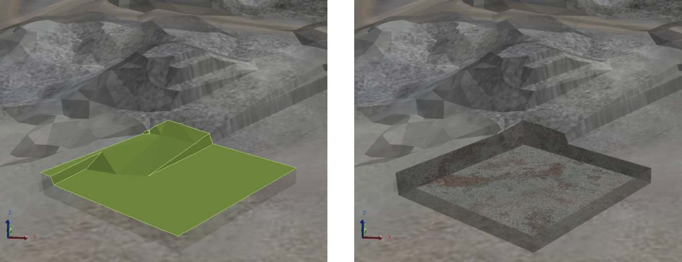
Before and after setting an activity area’s Activity to Mined-Out.
Apply a mined-out status
You can apply mined-out status in three ways:
-
Create a new mined-out area to represent recently mined ground that currently isn’t reflected by the topography. A mined-out area can cut into an existing activity area to reflect its mined status.
-
Convert an activity area to mined-out (for example, changing a dig area to mined-out)
-
Convert a portion of an activity area to mined-out
Each option is guided by the use of bucket positions.
Bucket positions
Bucket positions record where actual digging has taken place in the pit. Captured from operational systems and imported into XECUTE through Data Feed In, they appear in the 3D scene as points that trace the movement of a digger’s bucket during excavation. These positions provide a reliable indication of mining progress and help form the basis for accurately updating the mined status of activity areas.
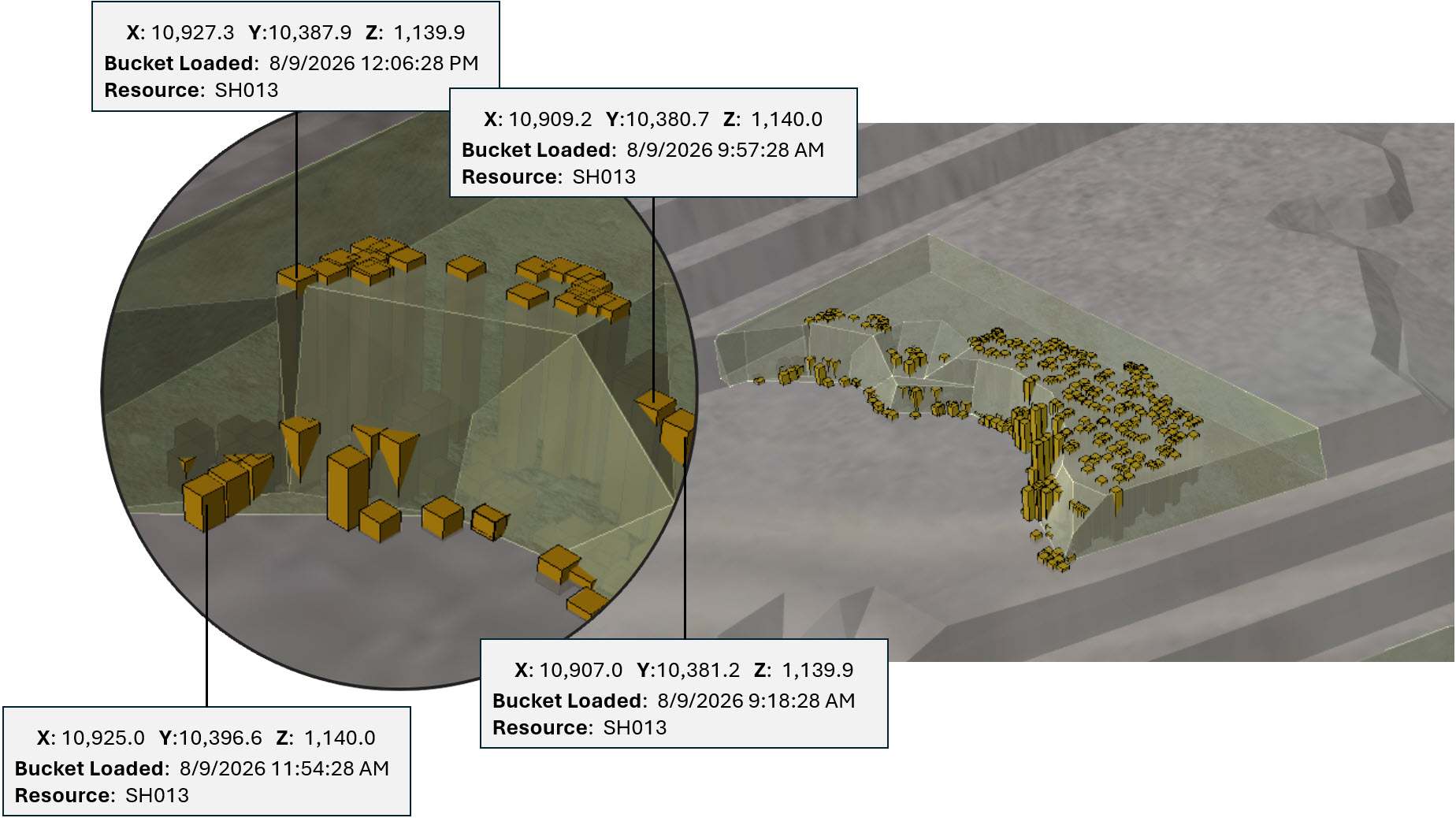
Bucket positions in the scene. The coordinates, resource name, and timestamp of some bucket positions are shown. You can use these bucket positions to trim the intersecting area off unmined activity areas. In other words, with bucket positions, you can automatically mark portions of activity areas as Mined Out – based on the real-life bucket positions of equipment items on site.
|
Resource |
Date |
X |
Y |
Z |
|---|---|---|---|---|
|
SH013 |
8/8/2019 11:06:28 PM |
10866.934934 |
10380.318294 |
1139.94 |
|
SH013 |
8/8/2019 11:03:28 PM |
10866.573114 |
10379.697488 |
1140.01 |
|
SH013 |
8/8/2019 11:00:28 PM |
10863.234896 |
10382.853208 |
1140.19 |
|
SH013 |
8/8/2019 10:57:28 PM |
10861.505286 |
10382.91639 |
1139.98 |
|
SH013 |
8/8/2019 10:54:28 PM |
10861.505286 |
10381.56639 |
1140.16 |
|
SH015 |
8/12/2019 12:36:28 PM |
10491.280972 |
10848.946471 |
1100.15 |
|
SH015 |
8/12/2019 12:33:28 PM |
10487.677215 |
10848.725778 |
1099.81 |
|
SH015 |
8/12/2019 12:30:28 PM |
10487.872418 |
10847.810736 |
1099.98 |
A demonstration of how bucket position data files are structured
By using bucket positions, you ensure that updates—whether trimming partially mined areas or converting fully mined ones—are driven by real operational data rather than assumptions. This keeps the schedule accurate and the model aligned with the current state of the mine.
Using bucket positions
Bucket positions are used to:
-
Identify which activity areas are fully mined and ready to be converted to Mined Out.
-
Determine how much of an activity area has been mined so you can trim only the depleted portion.
-
Guide the creation of new mined-out polygons when the topography has not yet been updated.
Without bucket positions, these updates rely on manual interpretation which can lead to errors or inconsistencies in the schedule.
Bucket position data
Bucket position data comes from your operational systems, typically through a Fleet Management System (FMS) or other high-precision GPS-enabled equipment tracking systems. These systems record the exact locations where a digger’s bucket interacts with the ground during excavation or loading. Records are captured at regular intervals (for example, every few minutes), so the dataset could contain thousands of points.
Data structure
The data is stored in a CSV file and must include the following fields:
-
Resource: The name of the equipment (e.g., SH013, SH014. SH015).
-
Bucket Position X: The X-coordinate of the bucket position.
-
Bucket Position Y: The Y-coordinate of the bucket position.
-
Bucket Position Z: The Z-coordinate of the bucket position.
-
When Bucket Loaded: The timestamp for when the position was recorded.
Each row represents a single bucket position, including the resource name, XYZ coordinates, and timestamp. Additional columns can exist in the file, but only the fields listed above are used by XECUTE.
Pulling the data into XECUTE
Bucket position data is imported into XECUTE using Data Feed In (DFI). The DFI configuration in Config establishes a live or scheduled connection to the source system, allowing bucket positions to be retrieved automatically as soon as they’re updated. Each point includes spatial coordinates and metadata such as timestamp and resource ID, which makes it possible to filter and visualise the data accurately.
Once received, the bucket positions are cached and displayed in the 3D Scene of Client. You can control their visibility and filtering through the Bucket Positions tab, ensuring that only relevant positions are used when trimming activity areas or creating mined-out polygons.
The bucket positions in XECUTE automatically update when the source updates. Only the visible bucket positions in the scene are considered during trimming operations.
Import the data
You pull in the data by setting up a DFI profile (go to Config > Site Edit ![]() > Data Feed In
> Data Feed In ![]() ).
).
The profile connects to an external source to automatically retrieve the data. For the selected external source, you set up a mapping, which tells the software how to interpret the data source.
1. Create a DFI profile
-
In Data Feed In
 , click Add.
 -
Set the name for the profile, then assign the profile to a spatial domain.
2. Set data type
-
Set Data Type to Bucket Positions.
-
Locate and select the data source.
-
For information about setting the Data Source, Definition, and Dataset, refer to Data Feed In.
3. Check the data preview
-
Review the preview to confirm the data source contains the expected columns and values.
-
Adjust the number of rows displayed if needed to avoid being overwhelmed by large datasets.
-
Check the Last Retrieval Result to confirm when the data was last updated and whether the retrieval was successful.
4. Set mappings
Map each system field to the corresponding column in the source file. For example:
|
Mappings |
|
|
Resource Name |
Map to the column that stores the resource names. |
|
When Bucket Loaded |
Map to the column that stores the timestamps or dates of capturing each bucket position. |
|
Geometry Type |
|
|
Bucket Position X |
Map to the column that stores the bucket position’s X coordinate. |
|
Bucket Position Y |
Map to the column that stores the bucket position’s Y coordinate. |
|
Bucket Position Z |
Map to the column that stores the bucket position’s Z coordinate. |
Additional Attributes lists fields that weren’t mapped or are remaining.
5. Save your changes
Save the DFI profile. Once saved, XECUTE will establish the connection and begin pulling in bucket position data automatically.
Visualising the data
After pulling in the data, you can visualise it to ensure that the data is accurate and correctly aligned with your site model.
When you visualise bucket positions, you can:
-
Confirm that the coordinates place each point in the correct location relative to topography, activity areas, and other spatial elements.
-
Check that the records match what you expect from the source system (e.g., correct resources, timestamps, and elevations).
-
Identify any anomalies, such as positions outside the pit or at unrealistic elevations, before applying trims or creating mined-out areas.
To visualise:
-
Enable Bucket Positions in the Scene Manager to display the shapes in the 3D scene.
-
Use the Bucket Positions tab to filter by resource, date, or other attributes so you only see relevant data.
-
Hover over a shape to view its details (coordinates, resource, timestamp) in a tooltip, or double-click a record in the tab to zoom to its location.
Accurate visualisation is important because only the visible bucket positions are used when trimming activity areas or generating mined-out solids.
Shape of bucket positions
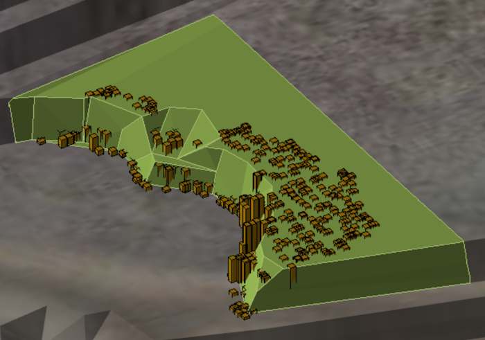
In the 3D scene, each bucket position is displayed as a 3D rectangle positioned according to its recorded X, Y, and Z coordinates. These shapes represent the exact points where the bucket interacted with the ground, making it easy to see where material has been mined and at what elevation.
Update mined status
Refer to the sections below for methods for converting activity areas. You can use any combination of these methods.
Use bucket positions to trim activity areas
You can trim an activity area using bucket positions. If bucket positions intersect or occur within an activity area, the software calculates a trim line based on the outer edge of a group of visible bucket positions – whole applying a small buffer.
Key considerations:
-
Bucket positions below the activity area’s mining level are ignored during trimming.
-
The filtered set of bucket positions determines the trim result, so always review filters before applying changes.
-
For large datasets, consider performance settings such as setting Calculation Mode to On Demand in Config.
You can perform three types of trims, which are detailed below.
Activity areas generated from cutting by bucket positions have an Import Source of Trim By Bucket Position (which you can see in the Activity Area properties).
Generate mined-out polygon
This option trims the activity area, by the shape of a group of bucket positions, and creates a new mined-out polygon for the depleted portion. The mined-out area is editable after trimming.
With this option, you can apply a Simplification Tolerance to reduce unnecessary vertices, in the existing activity area and the new mined-out activity area. A tolerance of zero means no simplification, while higher values simplify the shape while maintaining overall accuracy.
This option does not consider Z elevations, so the trim creates vertical walls between mined and unmined areas.
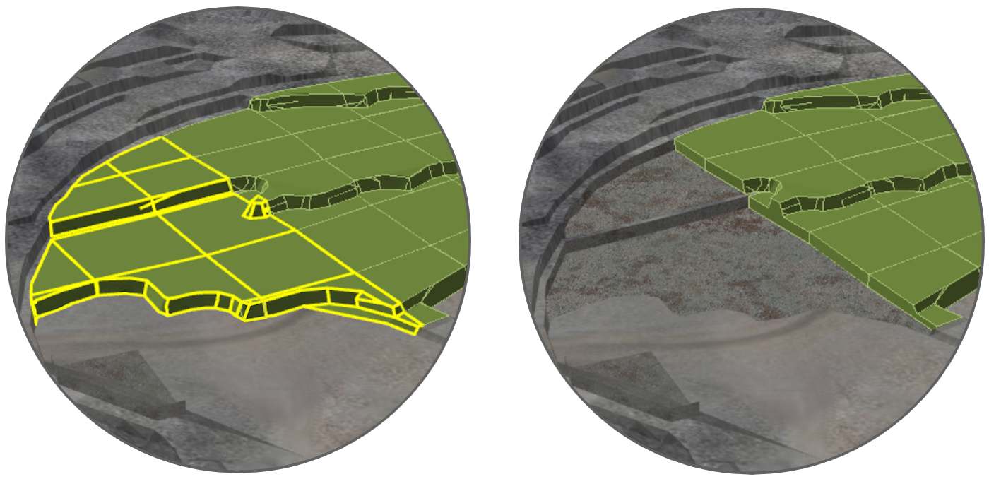
Before and after using the Mined Out Polygon option. There is a new activity area, with the Mined Out activity, where the group of bucket positions overlap the existing activity area. You can edit the shape of both activity areas afterwards.
Generate mined-out solid
Like the previous option, this one trims the activity area by the shape of a group of intersecting bucket positions. However, the Z coordinates of the bucket positions are also considered. The vertical extents of the mined-out portion are based on the actual elevations of the bucket positions, producing a more realistic representation of the mined surface.
Unlike the polygon option, the resulting solid cannot be edited after creation.
Before and after using the Mined Out Solid option. The mined-out activity area solid is based on the geometry of the intersecting group of bucket positions. As the bucket positions’ Z-coordinates are considered, the solid has varying elevations – providing the most accurate representation of mining that’s occurred.
No mined-out area (trimmed with polygon)
This option divides an activity area by the shape of a group of bucket positions. However, no-mined out shapes are created. Instead, the activity area is split into two – and the new activity area inherits
This option divides the activity area by the intersection of a group of bucket position shapes. However, no mined-out shapes are created. Rather, the activity area is split into two. The new activity area inherits a new profile, following the default conventions of the activity.
You can edit the shape of the activity areas after, like usual.
Before and after using the Mined Out Solid trim option
How to use bucket positions to trim activity areas
1. Follow the procedure above to pull the bucket position data into XECUTE.
2. Go to Client > Bucket Positions tab.
3. Use the filter options to visualise which bucket positions that will be used to trim the activity areas.
4. In the scene, locate an activity area with a group of intersecting bucket position shapes.
5. Select the activity area, right-click it to open the radial menu, then select Trim ![]() .
.
6. On the menu, select a trim option, then click Trim.
7. Validate the result of the trim in the scene.
Converting fully mined activity areas
When an activity area is completely mined—typically indicated when bucket positions fully enclose its shape—you can update its status in two ways:
-
Use one of the bucket position trim options described earlier.
-
Or, simply change the activity type to Mined Out.
Converting an activity area to Mined Out removes it from the schedule and updates the topography to reflect the mined-out state.
Before and after trimming an activity area fully enveloped by bucket positions – or converting its activity to Mined Out.
Convert an activity area to fully mined
-
Open Client and select the activity area in the 3D scene.
-
Enable visualisation of bucket positions to confirm that they fully enclose the activity area.
-
Choose one of the following:
-
Apply a bucket position trim option (if you want to maintain a record of the trim operation).
-
Or manually change the activity type: (right-click > Change Activity
 > Mined Out.
-
Once applied, the software converts the activity area to mined-out status and cuts it into the topography, ensuring the 3D scene and schedule reflect the current state of the pit.
Draw a mined-out activity area
If bucket positions are unavailable, you can manually define mined-out areas. When doing so, you have the option to trim existing activity areas, effectively removing portions that have already been mined.
Settings to use while drawing
-
Activity: Set to Mined Out.
-
Overlaps Option: Choose Remove From New Area to ensure overlapping mined-out sections are trimmed from the new area.
Steps
Draw a mined-out activity area
-
Open Client and go to the scene.
-
Use the option to create an activity area (right-click the scene, then select Draw Activity Area
 ).
). -
Set Overlaps to Remove From New Area.
-
Set Activity to Mined Out.
-
Define the shape and location of the mined-out area manually.
-
Save the activity area.
For detailed steps on creating activity areas, refer to the guide: Creating Activity Areas.